PCB (Printed Circuit Board) for PIC18F452 and 3COM 3C509B Ethernet ISA card
1. What? :
At the moment I'm workig at a project where I have connected a PIC18F452 with a 3COM 3C509B Ethernet ISA card. I had build everything on a experiment-board. However, I want to build a second-one, so that I can put one online and experiment with the second-one.
However, I was not in the mood to build this on an experiment-board. So, it was time to try to design a PCB-board for it. With free(dom) software and Debian GNU/Linux off course ;-)
2. The software that I have used :
You can find the software that I have used at the website of the gEDA project. With the information on this website it is not so difficult to start using the software.2.1. gschem :
I have drawn the electrical schematic with gschem. Note that when you later on want to make a PCB out of a schematic, it is necessary to attach a "footprint attribute" to every component. This footprint describes the 'mechanical properties' of a component.2.2. gsch2pcb :
At utils you'll find gsch2pcb. With gsch2pcb you create a .pcb-file out of a schematic that you have made with gschem. You can then use this .pcb-file with the program pcb.2.3. pcb :
With the program pcb you can desing the PCB-board. Once the PCB-board is ready, it is possible to create for example "Extended Gerber RS-274-X"- and "Excellon/NC drill" files which can be used by a PCB-manufacturer the build the PCB=board.2.4. gerbv :
The program gerbv is a viewer for this "Extended Gerber RS-274-X"- en "Excellon/NC drill" files.2.5. Remarks : components/footprints :
You don't get that much libraries and component files with gschem and pcb. Off course you can make this yourself. I have created the footprint for the ISA-connector and the PIC18f452-symbol myself. This is not that difficult, however, without RTFM I would not have managed it. But hey, I always RTFM with a nice hoegaarden, so, it was pleasant to do ;-)3. Making the PCB-Board :
I have let make the PCB-board at www.eurocircuits.be. This was not that simple, because you can only use this website with IE.
More info about how I have worked around this problem is available here.
4. The result :
The PCB manufacturered by www.eurocircuits.be looks like this :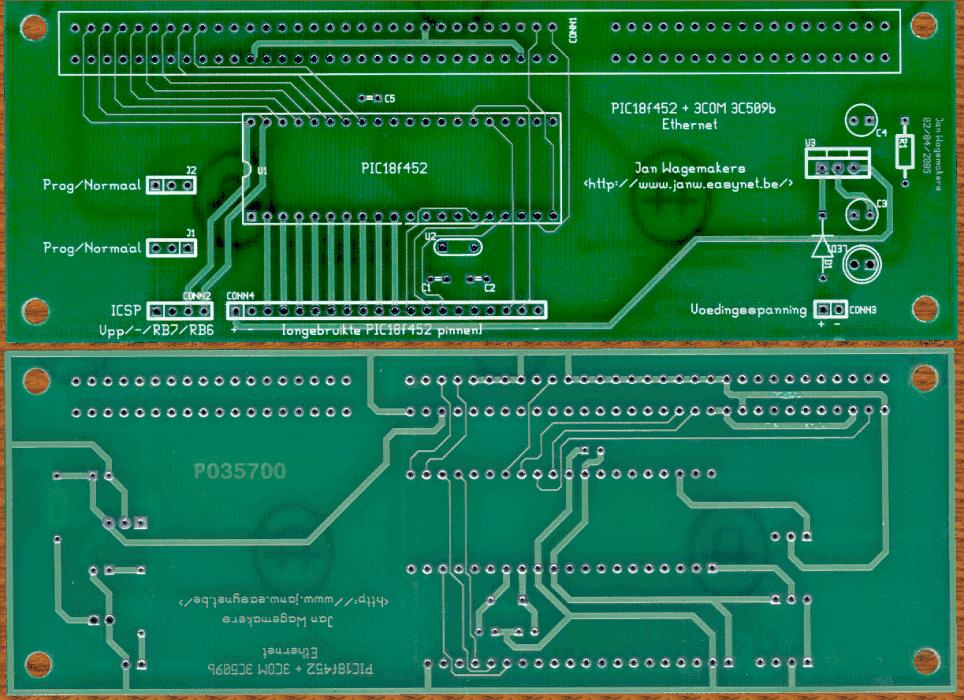
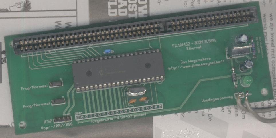
When I tried to put the components on this PCB, I discovered that I have forgotten to check the diameters of the holes. Some holes where not big enough. The voltage-regular, diode, resitor and jumpers doesn't fit in the holes. I have managed to solve this with a few tricks.
Off courses, this problem is totally my own fault. I should have checked this. But hey, this is a nice lesson that I have learned for the next PCB :-)
5. Downloads :
I have changed my files so that the holes are big enough now. You can download this files here. The .gbr's are the "Extended Gerber RS-274-X"-files ad the .cnc's are the "Excellon/NC drill" files.
Note that I have not let make this second revision. I think that there are no issues now, but it is possible that some things can be improved. Suggestions are welcome!